Chapter 3: The hardware interface, I/O and communications
3.2 Device interfaces
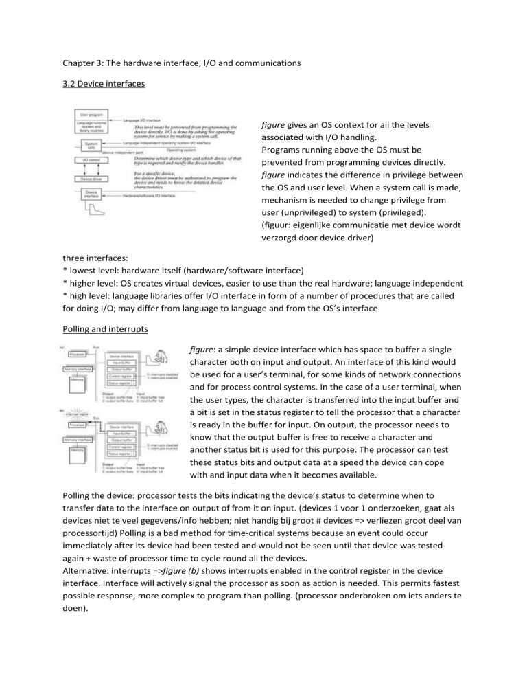
figure gives an OS context for all the levels
associated with I/O handling.
Programs running above the OS must be
prevented from programming devices directly.
figure indicates the difference in privilege between
the OS and user level. When a system call is made,
mechanism is needed to change privilege from
user (unprivileged) to system (privileged).
(figuur: eigenlijke communicatie met device wordt
verzorgd door device driver)
three interfaces:
* lowest level: hardware itself (hardware/software interface)
* higher level: OS creates virtual devices, easier to use than the real hardware; language independent
* high level: language libraries offer I/O interface in form of a number of procedures that are called
for doing I/O; may differ from language to language and from the OS’s interface
Polling and interrupts
figure: a simple device interface which has space to buffer a single
character both on input and output. An interface of this kind would
be used for a user’s terminal, for some kinds of network connections
and for process control systems. In the case of a user terminal, when
the user types, the character is transferred into the input buffer and
a bit is set in the status register to tell the processor that a character
is ready in the buffer for input. On output, the processor needs to
know that the output buffer is free to receive a character and
another status bit is used for this purpose. The processor can test
these status bits and output data at a speed the device can cope
with and input data when it becomes available.
Polling the device: processor tests the bits indicating the device’s status to determine when to
transfer data to the interface on output of from it on input. (devices 1 voor 1 onderzoeken, gaat als
devices niet te veel gegevens/info hebben; niet handig bij groot # devices => verliezen groot deel van
processortijd) Polling is a bad method for time-critical systems because an event could occur
immediately after its device had been tested and would not be seen until that device was tested
again + waste of processor time to cycle round all the devices.
Alternative: interrupts =>figure (b) shows interrupts enabled in the control register in the device
interface. Interface will actively signal the processor as soon as action is needed. This permits fastest
possible response, more complex to program than polling. (processor onderbroken om iets anders te
doen).
processor is fetching and executing instructions
from an arbitrary program when it receives an
interrupt signal from a device. Assuming that
handling the device is more important than
continuing to execute the program, an interrupt
should occur from the program to an interrupt
service routine. The processor state of the interrupted program is saved on the interrupt so that the
processor can be used by the interrupt routine. The saved state must be restored by the time the
program is resumed.
figure: typical CISC (complex instruction set
computers) mechanism; the program counter (PC)
and processor status register (PSR) are saved by
hardware. At the end of the routine, assuming we
are to return immediately to the interrupted
program, a special return instruction will restore
both the PC and the PSR. Any other registers that
are used by the interrupt service routine are saved
at the start of the routine and restored at the end
of the routine by software. The hardware
mechanism may cause writes to memory in order to store the PC and PSR. (a: before interrupt; b:
after interrupt) (snelheid van geheugen vormt problem (geheugen hier = RAM); duurt ong 50
nanosec om iets uit geheugen te halen, snelheid processor ong 1 gigaherz => 1 nanosec; we zouden
dus elke nanosec een nieuwe opdracht kunnen doen, maar voor 1 interrupt al 3x 50 nanosec nodig
=> bottleneck)
Interrupt handling: priorities
each source of interrupt signal is assigned a priority. The
processor status register indicates the priority level at which
the processor is executing. An interrupt signal with a higher
priority causes an interrupt; an interrupt signal with a lower
priority is held pending until the higher-priority interrupt
service routine has finished. Nested interrupts are handled
by using a stack structure; the PC and PSR are stored on a
stack each time an interrupt occurs and restored from the
stack when a return from interrupt instruction is executed.
(als er tijdens interrupt een nieuwe interrupt optreedt, wordt tabel met niveaus gebruikt om te
kijken of nieuwe interrupt belangrijker is dan oude)
Each device has an associated interrupt service routine. When an interrupt is to take place, the
address of the correct interrupt routine must be set up by hardware in the PC. The device interface
identifies itself when sending an interrupt signal to the processor, and this allows the correct service
routine address to be selected from the table.
Assembly language: bij wijze van spreken rechtstreeks hardware programmeren, quasi machinetaal.
Vroeger gebruikt om OS te schrijven, nu enkel nog voor device drivers.
Simpele instructies veel gebruikt, complexe weinig.
RISC (reduced instruction set computers) => programma’s worden langer, maar wel sneller door
gebruik van enkel simpele instructies
pipelining: uitvoering kan overlappen met andere instructies
The RISC approach to interrupt handling
figure shows support for exception handling in the on-chip system control coprocessor of the MIPS
R2000/3000. The cause, status and exception program
counter (EPC) registers are shown in more detail in the
figure. The status register contains a three-level (six-bit)
stack; each level has a processor status bit (privileged;
unprivileged) and a global interrupt enable/disable bit.
the exception handling mechanism:
* puts the resume address for the interrupted process in
the EPC register;
* pushes a new two-bit entry onto the six-bit stack, this
sets the processor status to privileged and disables
interrupts globally;
* sets up the PC to the address of one of three exception-handling routines.
The return from exception (RFE) instruction pops the status stack by two bits.
(MMU: memory management unit)
(aangeduide registers voor exception handling (3), werkt tegen snelheid van processor zelf (want zit
op chip); tijd om iets van schijf te halen ong 10 millisec (= tijd van 1 toer): traag! => bottleneck!)
Direct Memory Access (DMA) devices
Will transfer a block of data into or out of memory and interrupt the processor only after the whole
transfer is complete (block-oriented devices: proberen blokken van gegevens in 1x te behandelen)
figuur: DMA => controller krijgt toegang tot geheugen
(rechtstreeks, zonder buffer); competitie tussen DMA en
processor om bus te kunnen gebruiken (kan maar 1 tegelijk
toegang tot hebben) => cycle stealing (during the transfer the
disk controller is transferring data to or from memory at the
same time as the processor is fetching instructions from memory
and reading and writing data operands in memory; memory
controller ensures that only one of them at once is making a
memory access)
cache wordt geplaatst om tijd dat de processor het geheugen
niet nodig heeft te maximaliseren; zorgt ervoor dat je niet altijd naar RAM moet => data en
instructies die recent gebruikt zijn, worden in cache gehouden omdat akns groot is dat je die snel
opnieuw nodig hebt, als dat zo is, kan processor die gwn uit cache halen en is bus naar geheugen vrij.
We proberen voor cache snellere technologie te gebruiken: SRAM ipv DRAM (5x sneller) (sneller
impliceert in principe ook kleiner, omdat het anders te duur wordt => grootte van cache hangt dus af
van gebruikte technologie en wat je kan betalen). Niveau 1/2/3 cache. Disk controller zet gegevens
rechtstreeks in geheugen en geeft pas interrupt als dit gebeurd is => processor hoeft niets meer te
doen
a disk controller is a simple processor with registers for holding the disk address, memory address
and amount of data tob e transferred. After this infromation has been passed to it by a central
processor, together with the instructions to proceed with the disk read or write, the disk controller
transfers the whole block between disk and main memory without any intervention from the central
processor. When the block transfer is complete, the disk controller signals an interrupt. The
processor can execute some other program in parallel with the transfer. A hardware- controlled
cache reduces contention (DMA slows down the rate at which the processor executes instructions).
scatter-gather allows the programmer to specify a number of blocks of data to be written to one
place on the disk by a single command (gather), or a single area of disk to be read into a numberof
memory locations (scatter).
Memory-mapped I/O
two approaches to transferring data to a device:
* by a special set of I/O instructions
* by memory-mapped I/O: physical memory addresses are allocated to device interfaces , and input,
output, status checking and control are achieved by reading and writing these memory locations. No
extra instructions are needed. (devices plaats geven in geheugen (virtueel) => registers van devices
krijgen adres alsof ze intern geheugen zijn)
Timers
a timer interface may be programmed to generate an interrupt after some period of time, then do
nothing until further instructed. Alternatively, it may be set up to generate interrupt periodically.
the rate at which interrupts are generated is programmable (rate ranges from 1 microsec to 65
millisec) (timer is ook soort device, geeft om de zoveel tijd een interrupt)
3.3 Exceptions
synchronous: if the program was restarted, the error would occur again at the same point;
predictable; in almost all cases the program cannot continue after the error condition has occurred:
must be handled first
asynchronous: device interrupts might or might not be handled immediately they occur, depending
on the relative priorities of the running program and the interrupting device; unpredictable, nothing
to do with running program
when a page fault occurs, it must be handled before the program can continue; that is, the page that
is being referenced must be transferred into memory by the OS. The page fault handling is
synchronous with the running program; (un)predictable
software interrupt: trap
(interrupts zijn typisch hardware interrupts, maar trap
is software interrupt)
user mode vs. system mode:
*user mode: privileged instructions are forbidden
(exception generated)
*system mode: privileged instructions are allowed
exception handling: exception mechanism sets state to
privileged, exception handling routine is executed in privileged mode
system call mechanism: switch from user mode to system mode needed; force system call to
generate exception using special instruction: trap or software interrupt; standard method for
entering OS
figure: sequence of events which illustrate nested interrupt handling and trap handling. A user
program is running when an interrupt from a device at priority level 3 occurs (1). The service routing
for that device is entered (2). As part of the transfer mechanism the PSR and PC of the user program
are saved and then set up for the interrupt service routines; the status register is set to level 3 and
privileged state. Part-way through execution of this interrupt service routine a higher-priority device
interrupts (3). Its service routine is executed (4). This completes and the interrupted PC and
processor status are restored to return to the interrupted level 3 routine (5). This completes and we
return to the interrupted user program (6). The user program makes a system call and a trap
instruction is executed by a library routine (7). The trap service routine is executed. The priority level
in the PSR is not changed but the state is set to privileged. The routine completes and control is
returned to the interrupted user program (8).
3.4 Multiprocessors
When a program runs on a processor, any (synchronous!) exceptions it causes are signaled to that
processor. These include errors, system calls and page faults.
An interrupt signaling the end of a DMA transfer may be handled on any processor.
If a user aborts a program, the processor that takes the interrupt must be able to interrupt the
processor on which the program is running; there is a requirement for inter-processor interrupts.
3.5 User level I/O
The application level can request input or output of an arbitrary amount of data; the device
concerned can transfer a fixed amount. Data buffers are needed between the I/O modules which are
invoked by the application (top-down) and those which are executed in response to device events
(bottom-up). The top-down software can place the
data to be output in one or more buffers. We then
need a mechanism for telling the lower levels that
there is work to do. Similarly, when a device delivers
data it is placed in one or more buffers by the low
levels and the high levels must be told there is work
to do. Requirement for processes to synchronize with
each other.
There is likely to be a buffer area for user terminals,
one for disk blocks, one for network communications,
and so on. The figure shows the data buffers as
abstract data types or objects. The device handler should be able to start work a.s.a.p. on a large
amount of output, before the top level has put it all into a number of buffers. Similarly, on input the
high level may be able to start taking data from a buffer as soon as one is full. Care must then be
taken that the processes synchronize their accessed to the buffers.
A synchronous I/O policy indicates that the user-level process is blocked when a delay is necessary
until the request can be satisfied (synchroon: als de gegevens er niet zijn, kan je niet verder, je doet
iets anders). Asynchronous: if a delay is necessary, control can be returned to the user-level process,
which can proceed with its work and pick up the requested input or acknowledgement of output in
due course (asynchroon: als gegevens er niet zijn, doe je iets anders – programma loopt verder).
In some systems, user-level processes can specify whether they require sync or async I/O when they
make a request.
3.6 Communications management
The network connection of a computer may be considered at a low level as just another device. It has
an interface and is handled by device-driving software.
In the case of communications handling, the network connection is shared. It is also bidirectional:
several local processes can request to communicate with external processes and their requests may
be in progress simultaneously; also, external processes may autonomously request to communicate
with local processes.
Blok oriented => DMA
figure: processes on different machines may need to
communicate with each other. Figure shows basic
requirement, process A on one machine, B on another.
The virtual communication, shown as direct between A
and B, may in practice be achieved by a system call to
the OS which organizes data transfers across the network: the real communication shown in the
figure.
3.8 communications software
The ISO reference model for Open Systems Interconnection
The reference model provides a framework for modular,
layered software. Each layer provides a service interface to
the layer above and protocols for communicating with the
corresponding layer in other systems.
figure: how ISO layers might be provided in a typical OS
Physical layer: transmitting uninterpreted bits across
communication channel from one computer to another;
managing the connection
data link layer: taking a raw transmission facility & turning it
into a link that appears free from errors
network layer: transmitting data from a source to a
destination across networks; determine route for packets +
avoid congestion by controlling number of packets
transport layer: transmission from end system to end
system; usually highest level of communication service ins
OS and session layer provides interface to OS’s communication service
session layer: allows clients of an OS on one machine to establish and use sessions with clients of an
OS on another machine
presentation layer: representation of data
application layer: number of standard protocols that are of general use (remote procedure call, FTP..)
3.9 communications handling within and above an OS
1
2
(1) commonly used protocol hierarchy in relation to the ISO layers in an Ethernet-based UNIX system.
need for sync between user-level processes requesting to send or receive data and the hardware
carrying out physical I/O; use of I/O buffers on input and output => similar sync and buffering
arrangements are needed for network I/O.
(2) examples of application-level protocols within an overall communications architecture. The mail
app is using a specialized protocol, SMTP (simple mail transfer protocol); web browser uses HTTP.
Other examples of special-purpose app protocols: FTP (file transfer protocol) and NNTP (network
news transfer protocol).
ethernet controller: alle gepriviligeerde instructies
die je kan geven via hexadecimale notatie
hexadecimale notatie:
vb: 0002 => 0000 0000 0000 0010
0400 => 0000 0100 0000 0000
RO: read-only
RW: read, write
RC: read, clear
Code van hoe interrupts afgehandeld worden
0xffff3579 => adres waarnaar processor schrijft
(geheugen)
wachten op bufferruimte bij verzenden


