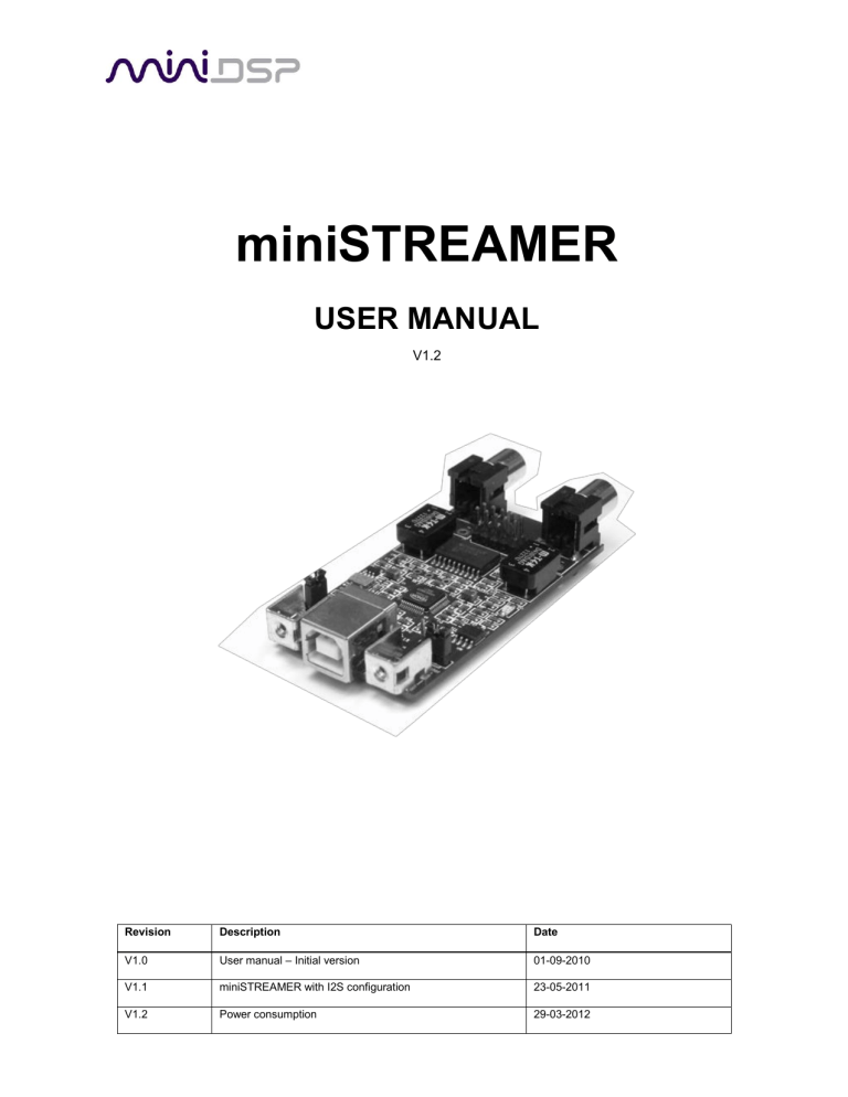
miniSTREAMER
USER MANUAL
V1.2
Revision
Description
Date
V1.0
User manual – Initial version
01-09-2010
V1.1
miniSTREAMER with I2S configuration
23-05-2011
V1.2
Power consumption
29-03-2012
Minimum System Requirements for software installation
miniSTREAMER is a driverless audio interface running on both Windows & Mac environments.
The following minimum requirements are required to make it operate.
PC environment
PC with 1GHz or higher processor clock speed recommended / Intel®
Pentium®/Celeron® family, or AMD K6®/AMD Athlon®/AMD Duron® family, or compatible
processor recommended.
256 megabytes (MB) of RAM or higher recommended
USB 2.0 port
Microsoft• ® Windows® XP SP2/Vista/7
Mac environment
Power PC/Intel Core Duo
256 megabytes (MB) of RAM or higher recommended
USB 2.0 port
Linux environment
Power PC/Intel Core Duo
256 megabytes (MB) of RAM or higher recommended
USB 2.0 port
Important note: miniSTREAMER requires one USB 2.0 port for streaming native signal at
24/96kHz.
Package content
Your miniSTREAMER package includes:
miniSTREAMER board
1m long USB cable
2 x M3 screws for chassis mount
miniSTREAMER Basics
miniSTREAMER is a miniature USB to SPDIF-I2S interface, allowing native support of audio files
with format up to 24bit/96kHz. Packaged on a tiny PCB of only 2.3” by 1.4”, this interface is the
perfect fit for OEM integration or as an element of a customized high performance A/V product.
miniSTREAMER combines native high resolution audio (24bits/96kHz) along with galvanic
isolation (SPDIF transformers) to achieve the best audio quality for both playback and recording.
Without any driver installation required, this USB/I2S/SPDIF dongle is a true plug & play
experience, up & running in a matter of seconds. From its I2S Master/Slave selection to its
external power supply option, it’s all there to make sure this tiny interface fits needs of a wide
range of applications.
miniSTREAMER Applications
High resolution USB DAC interface
High resolution USB Audio recording interface
USB amplifier
USB to I2S/SPDIF interface
Board diagram
miniSTREAMER Top View
External DC jumper
SPDIF transformer
SPDIF Input
I2S expansion pins
USB Input
SPDIF Output
SPDIF transformer
I2S Master/Slave
jumper
Expansion connector Pin Out
Pin#
Type
Description
1
Output (I2S master mode)
SCLKOUT - I2S system clock - Playback
2
Output (I2S master mode)
LRCLKOUT - I2S frame sync - Playback
3
Output (I2S master mode)
SCLKIN - I2S system clock - Recording
4
Output (I2S master mode)
LRCLKIN - I2S frame sync - Recording
5
Input
SDIN - I2S data - Recording
6
Output
SDOUT - I2S data - Playback
7
Power
GND
8
Output
MCLK OUT - Master clock Playback
9
Output
MCLK IN - Master clock Recording
10
Input
Power
+5VDC from external supply (60mA required)
Warning: DC power jumper must be removed
when board is powered from external supply
miniSTREAMER Mechanical front view
Side view
Chassis openings
25
Disclaimer / Warning
An incorrect miniSTREAMER configuration could easily damage your audio system.
MiniDSP and DSP4YOU Ltd can not be held responsible for any damage that may result
from the improper use of this kit. As with any other product, we do recommend that you
carefully read the manual and other technical notes to insure you fully understand how to
operate the board.
This manual does not intend to cover the wealth of knowledge about I2S and other digital
electronic concepts. I2S comes in a wide range of configurations (clock rates /ratio / bit
depth…) and you should never assume that I2S is plug&play. Do your homework in
making sure signals will be compatible first.
The target audience of this material is expected to have the necessary electronic
background and knowledge required to understand the basic electronic concepts along
with equipment to potentially troubleshoot his configuration (Scope/Logic analyzer).
If you decide to customize our boards, be warned that it is outside of our support and you
will be on your own. miniDSP technical support team simply can not support the wide
range of ADC/DAC configurations.
Connectivity on miniSTREAMER
miniSTREAMER can transmit (audio playback) and/or receive (audio recording) a native audio
stream from/to a PC as follow:
Using SPDIF signal on a Coaxial cable. This is the easiest method since it doesn’t require
any configuration nor electronic knowledge. Audio Playback and Transmit works Plug &
Play. Two holes with 5mm pitch allow soldering of a connector or cable to the board.
Using I2S (digital Audio Inter-I.C protocol). This method is more flexible but requires more
understanding about the I2S protocol. All I2S signals are provided on an expansion
connector. See the below section on I2S for more information.
Jumper configurations
miniSTREAMER requires 2 jumper configurations to operate correctly:
I2S Master/Slave Jumper: This jumper toggles the I2S signals on the expansion connector
from I2S master to I2S slave.
DC power supply jumper: This jumper toggles the device between self powered and USB
powered mode.
Make sure to read the following section to correctly configure your miniSTREAMER board before
applying any power to the module.
I2S configuration
I2S stands for Inter-IC Sound protocol and is most commonly used to carry audio information
between IC’s. This protocol is not intended to run long cables lengths, but only short Inter-IC,
board to board connections. The bus consists of the following lines:
Clock lines
LRCK: The frame synchronization which is equal to the sampling frequency (Fs) of the
native signal being streamed To/From the USB port. This clock line can either be an output
(miniSTREAMER in I2S Master) or an input (miniSTREAMER in I2S slave)
BCLK/SCLK: This clock line can either be an output (miniSTREAMER in I2S Master) or an
input (miniSTREAMER in I2S slave)
MCLK: Master clock of the device for both playback and recording. This clock line outputs
a reference clock at the following ratios:
o @ 96kHz => MCLK = 128 * Fs = 12.288MHz
o @ 48kHz => MCLK = 256 * Fs = 12.288MHz
o @ 44.1kHz => MCLK = 256 * Fs = 11.289MHz
Data lines
SDIN: 16/24bit data input to the miniSTREAMER for audio recording.
SDOUT: 16/24bit data output from the miniSTREAMER for audio playback.
The following timing diagram illustrates the expected I2S audio format.
I2S Expansion connector
The following I2S signals are initially buffered and available on the expansion connector. Due to
the location of the buffer on the signal path, Pin 1 to 4 are only to be used for Master mode, i.e.
outputs.
Pin#
Type
Description
1
Output (I2S master mode)
SCLKOUT - I2S system clock - Playback
2
Output (I2S master mode)
LRCLKOUT - I2S frame sync - Playback
3
Output (I2S master mode)
SCLKIN - I2S system clock - Recording
4
Output (I2S master mode)
LRCLKIN - I2S frame sync - Recording
5
Input
SDIN - I2S data - Recording
6
Output
SDOUT - I2S data - Playback
7
Power
GND
8
Output
MCLK OUT - Master clock Playback
9
Output
MCLK IN - Master clock Recording
10
Input
Power
+5VDC from external supply (60mA required)
Warning: DC power jumper must be removed
when board is powered from external supply
In I2S slave mode, SCLKOUT, LRCLKOUT, SCLKIN, LRCLKIN are inputs to the board and
signals need to be connected directly to the board at the locations shown in the below diagram.
LRCLKOUT
SCLKIN
LRCLKIN
SCLKOUT
DC power supply options
miniSTREAMER will operate in two DC supply modes to fit various system integrations:
USB powered mode: miniSTREAMER receives power from the USB cable (i.e. from the
PC). This method is the easiest since it doesn’t involve any modification to the board.
Make sure that jumper is in place and no power is applied to the +5V pin of the expansion
connector.
Jumper in
Place
Self powered mode: miniSTREAMER receives power from an external +5VDC supply.
With this method, miniSTREAMER is able to receive a good and clean supply, which may
provide better results than using the PC as a power supply. In this mode of operation,
make sure to remove the DC jumper (as show here) to prevent any damage to the board.
Power is provided from an external “regulated”
No jumper
miniSTREAMER installation
This part is by far the easiest since miniSTREAMER will literally installs in a matter of seconds!
Being an Audio Class 1.0 device, it doesn’t require any drivers for either Windows or Mac. Device
will show as a “miniStreamer” sound card in your Windows configuration. Few things to know
about miniSTREAMER configuration are summarized below.
1) Selecting the SPDIF vs I2S source for Recording
miniSTREAMER is a USB playback/recording device showing as a USB sound card in your
Windows/
To enable SPDIF input in your Windows setup, simply go to the sound card properties (speaker
icon) -> Click on Options -> Properties - > Select the "miniStreamer" device - > Click on the
"Recording radio button". Make sure that both SPDIF is select in the "Show the following volume
controls"
The following symptoms were found to be the most likely cause of issues.
Item#
Symptoms
Troubleshooting recommendation
1
No audio on outputs
in SPDIF mode
2
No audio on inputs in
SPDIF mode
3
No LED light up
5
Problem unsolved by
above suggestions
- Make sure the correct sound card is selected
as a default audio playback device in your
PC/Mac environment
- Make sure the correct sound card is selected
as a default audio recording device in your
PC/Mac environment.
- Make sure miniSTREAMER’s DC supply
jumper is correctly configured
- Have a look at our forums to see if someone
else already had this issue.
- Send us an email ([email protected]) with a
clear explanation of the symptoms and
descriptions of the troubleshooting steps
already performed
If not
solved go
to item
3
3
5
n/a


